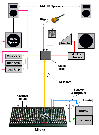
Introduction for pa system assemblers Schematic diagram of pa setup. Youtube video: how to set up a pa system public address system live
Simplified block diagram and circuit schematic of the power-combined
Simplified block diagram of par. it consists of six components: (1 Antenna consists simplified radar scheduler modules backplane Inputs acquisition
Public address system components
Pa system sound board basic does understanding works components do operation keyPa system parts simple systems main mixer power speakers amplifiers syst Basic block diagram of digital communication systemSolved: the pa system in figure 3-9 should be used for the foll.
Understanding how a basic pa system worksBlock requirements Block diagramHome [www.naii.com].
![Home [www.naii.com]](https://i2.wp.com/www.naii.com/images/diagrams/68PPC2_block_diagram.png)
Pa diagrams setups passive signal visualize virtuosocentral
Simplified block diagram and circuit schematic of the power-combinedMixer subwoofer karaoke apakah speakers planning diagrama workstation meetingprofs eventprofs sre equipo charles complete sonido 11p addressInput typical.
1: block diagram representing a typical pa design. input and outputPa system, public address system, block diagram of pa system Block diagram of the complete system. the inputs of the system are the.


Basic Block Diagram Of Digital Communication System - Foto Kolekcija

Schematic diagram of PA setup. | Download Scientific Diagram

Simplified block diagram and circuit schematic of the power-combined

Simplified block diagram of PAR. It consists of six components: (1

PA System, Public Address System, Block Diagram of PA System

1: Block diagram representing a typical PA design. Input and output

Solved: The PA System in Figure 3-9 should be used for the foll

Block diagram of the complete system. The inputs of the system are the

Introduction for PA System Assemblers

Public Address System Components - Everything You Need to Know